

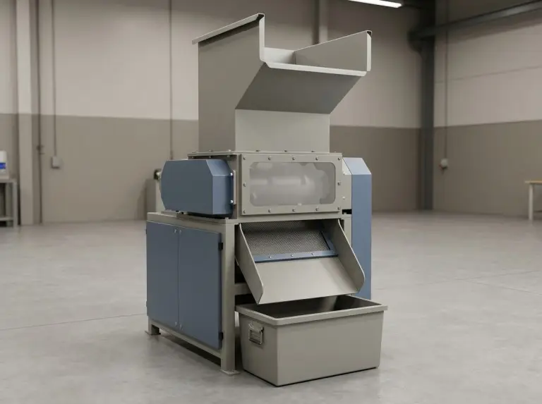
Designing a plastic crusher for recycling starts with defining the feedstock, output goals, and operating profile. At IPG, we treat the machine as a controlled cutting system. It must match real material behavior. This mindset aligns our choices for machine type, chamber layout, and commissioning checks.
Plastic streams that look similar can load a cutting chamber differently. Film tends to wrap, while thick rigid parts can spike torque if hard contaminants enter. We clarify what to verify at the hopper and screen because most “unexpected failures” start at the feed boundary.
Search results often mix terms like crusher, shredder, and granulator. Here, “plastic crusher” refers to a knife-and-screen unit that reduces material for downstream processing. Verify naming and scope against your required output and actual line interface.
Design Inputs and Output Requirements
Design becomes repeatable when you define feed behavior, output acceptance, and integration limits clearly. We lock these inputs before choosing a rotor, knife layout, or screen. This prevents the common mistake of picking a crusher type before characterizing the feedstock.
Feedstock profile and contamination checks
Your profile must describe form and handling behavior, not just the polymer family. We separate film, bottles, thin-wall parts, thick parts, and mixed scrap. Each form changes engagement and flow. Mixed streams work, but you must define the operating window explicitly.
Contamination assumptions guide wear strategy and overload protection. Sand, metal, or dust can change failure modes from “slow wear” to “edge chipping.” Verify contamination levels by sampling, not by assuming supplier descriptions are correct.
Output form and size control intent
State whether the line needs flakes or granules. Define how sensitive the next step is to dust (fines). Washing, conveying, and melting respond differently to size spread. Confirm acceptance with the process owner. “Looks fine” can still fail during conveying or filtration.
Screen selection affects output size, but stability also depends on knife condition and material flow. Smaller openings increase time in the chamber and cutting passes. This improves uniformity if the cut stays in shear. If the cut shifts to tearing, fines and heat rise. Verify this behavior in trials.
Duty cycle and feeding method
The operating profile matters. Plastic cutting behavior changes under continuous load versus intermittent bursts. Start-stop frequency, surges, and overloads affect heat and vibration. Define duty cycles early to set drive strategy and protection settings.
The feeding method controls load consistency. Manual dumping, conveyors, and batch drops create different surge patterns and flyback risks. Verify feeding behavior with actual operator practice, not just written procedures.
Line integration and maintenance access
Line integration defines how material enters and exits. These constraints often shape the hopper and discharge more than the cutting chamber does. A backed-up discharge forces recirculation, which triggers wrapping or clogging. Confirm discharge handling early. Congestion downstream often looks like “bad cutting.”
Maintenance access is a core design element. Blade changes, screen swaps, and cleaning must happen without long disassembly. Verify access assumptions against real site clearance and tools.
Input pack we ask for during design review
- Feed description: dominant forms, mix variability, contamination notes (verify by sample)
- Output intent: flakes vs granules, size control, fines sensitivity
- Operating profile: duty cycle, feeding method, surge risk, clearing expectations
- Integration limits: discharge handling, space, guarding, service access
Main Plastic Crusher Types and Uses
Select a crusher type by mapping it to a dominant feed form and failure mode.We use “typical uses” for the first pass, then verify the operating window with real feed. Final selection depends on stream variability and output strictness.
Claw crushers for thick rigid scrap
We choose claw-style cutting for thick rigid parts that need strong bite-in engagement. This style handles solid chunks without relying on material tension. Load stability depends on feed presentation. A single oversized lump can create a torque spike.
Rigid scrap often hides hard inclusions. Define your wear and protection strategy early. Verify contamination risk and how you manage overloads. Also verify screen clearing, as heavy fragments can rebound and circulate.

Flake crushers for bottles and thin-wall parts
Flat-blade styles work best for bottles and thin-wall containers. A cleaner, scissor-like shear reduces uncontrolled tearing. Stable presentation to the knives is vital. Irregular engagement increases fines and noise. Output cleanliness depends on blade condition, screen choice, and fracture tendencies.
Mixed streams can shrink the operating window. Labels, straps, and film in bottle streams can trigger wrapping. Verify the real mix before locking a fixed knife and screen configuration.
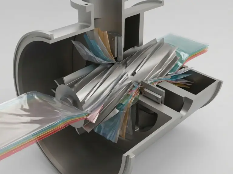
Film crushers for soft film and bags
Film designs focus on wrapping and bridging risks. The goal is keeping film re-entering the shear zone. Without flow control, film compresses into balls, clogs screens, or rides on rotors. Feeding stability and flow guidance matter more here than raw power.
Film behavior changes with thickness and moisture. Loose bags, covers, and densified film behave differently. Verify anti-wrap performance with representative film, not a simple sample.
Cutting Chamber and Material Flow Design
The cutting chamber determines stability by controlling engagement, residence time, and discharge. We design around how plastic reaches the shear zone, exits through the screen, and contains rebound. This links rotor layout, speed, screens, and hoppers into one path.
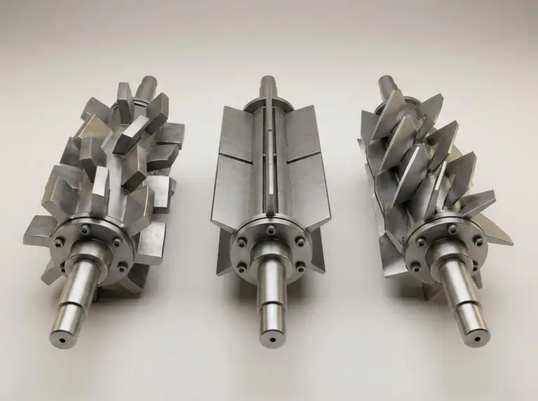
Rotor and knife layout
Match the rotor and knife layout to the dominant feed. Some feeds need controlled shear with repeated presentation. Others need aggressive engagement to avoid stalling. We define the expected failure mode first, then design to prevent it.
Knife layout must reflect feed shape behavior. Thin film stretches and wraps. Rigid parts rebound and fracture. Verify that chamber geometry encourages re-entry into the shear zone rather than uncontrolled circulation.
Speed and torque strategy
Speed and torque strategy trades throughput against byproducts like fines, noise, and heat. Higher speed cuts more often but increases dust if material fractures. Lower speed improves torque and reduces noise but may reduce capacity.
We prefer a strategy that tolerates realistic variance. Variable control helps, but benefits depend on drive sizing and feeding stability. Verify control behavior under real overload conditions.
Screen selection and discharge flow
Screens control output size and residence time. Smaller openings improve consistency but raise heat and clogging risks if feed smears. Larger openings boost throughput but increase size spread. Verify downstream tolerance.
Discharge flow is part of the system. Backed-up discharge changes chamber behavior. Bins and conveyors can force recirculation. Verify discharge handling early, as discharge problems are often misdiagnosed as cutting issues.
Hopper design and anti-wrap handling
Hopper geometry must guide material into engagement and limit flyback. Rigid pieces rebound differently than film. Verify hopper performance with representative feed. Guarding must match real loading and jam-clearing habits.
Anti-wrap handling is a flow problem. Wrapping accelerates when partial blockage reduces screen open area. Verify wrapping tendency during trials and adjust the flow path before pushing throughput.
Decision point | What it can improve | What it can worsen | What we verify in trials |
|---|---|---|---|
Higher speed strategy | Throughput potential | Fines, noise, heat | Dust trend and temp rise |
Smaller screen openings | Size consistency | Heat, clogging risk | Blockage with real feed |
Aggressive engagement | Pull-in of rigid scrap | Torque spikes, rebound | Overloads and flyback |
Flow-focused hopper | Feeding stability | Footprint constraints | Bridging risk |
Wear, Sealing, and Serviceability
Reliability depends on wear control, dust exclusion, and access for operational benefits.We design paths so routine work stays routine. Actual wear depends on contaminants and discipline. Verify this with early inspections.
Knife wear and sharpening strategy
Balance edge holding and impact toughness. Plastic streams often contain hard inclusions. We avoid fixed life claims because performance varies. Inspect early wear patterns to confirm if the cause is abrasion, chipping, or heat.
Sharpening discipline affects fines and heat. Dull edges shift the cut from shear to hammering. Output drift and noise often signal edge degradation. Define inspection triggers rather than time-based promises.
Chamber stiffness and gap stability
Chamber stiffness prevents deflection that alters the cut. Gap stability influences quality, vibration, and safety. We design for stiffness and verify stability after the first maintenance cycle.
Wear protection should focus on surfaces that set alignment and flow. Wear here changes residence time and fines. Verify protection effectiveness by inspection, not by assuming material thickness is enough.
Bearings, seals, and dust isolation
Bearing failures often start with dust and heat, not just lubrication issues. We isolate dusty zones from supports and select sealing to match the load. Verify seal performance with early temperature and noise trends.
Lubrication only works if you control contamination entry. Repeated overloads also accelerate damage. Verify overload behavior against real feeding methods.
Service access for blades and screens
Design serviceability around frequent tasks. Blade access, screen removal, and cleaning must fit site limits. Verify access routes and lifting tools early. “No space to service” means long downtime later.
A practical documentation pack reduces delays. We define assembly intent, inspection points, and service notes. Verify documentation scope for each project.
Verification Checklist Before and After Commissioning
Commissioning reduces risk when you tie checks to design assumptions. Use pre-start checks, trials, and monitoring to find hidden issues. Repeat verification when the feed mix or output acceptance changes.
Commissioning verification block
- Pre-start: Guarding, fasteners, knife seating, screen mounting, access paths
- Trial run: Feed stability, rebound, wrap/bridge tendency, discharge
- Trend checks: Vibration, temperature rise, abnormal noise
- Output checks: Size consistency, fines trend vs tolerance
Pre-start safety and mechanical checks
Checks prevent damage often misread as “bad cutting.” Confirm knife installation, screen seating, and fastener security. Verify guarding matches real operator access.
Confirm lockout and safe access with the maintenance team. A safe design fails if the process encourages unsafe jam clearing. Verify practices alongside hardware.
Trial run observations with real feed
Use representative feed for trials, not clean samples. Watch if material enters the shear zone or recirculates. For film, look for early wrapping and screen blockage.
Adjust feed rhythm before pushing for throughput. A stable chamber at moderate feed predicts success better than a short peak test. Verify stability across the mix range.
Trend monitoring: vibration, heat, noise
Focus on trends, not absolute values. Baselines vary by installation. Rising vibration, heat, or new noise can indicate loosening or contamination. When trends appear, reduce load and inspect.
Tie monitoring to maintenance. Monitoring without action allows damage. Verify response procedures during the first weeks.
Output acceptance and drift checks
Confirm that the screen and cutting mode produce acceptable regrind. Check size spread and fines against downstream sensitivity. If output drifts, check blade condition and screen blockage first.
Verify acceptance with downstream processing. Conveying and melting reveal issues a bucket sample misses. When acceptance tightens, review settings.
FAQ
Questions usually trace back to feed mismatch, instability, or maintenance. We answer with a conclusion, then conditions and verification steps. Each answer depends on your mix and environment.
What causes film wrapping on the rotor?
Wrapping means film strands ride the rotor instead of entering the shear zone. First, verify feed presentation and surge feeding. Bridges can trigger wrapping even with sharp knives. Also check for screen blockage, which accelerates wrapping.
Why does output size drift with the same screen?
Drift usually comes from blade changes or partial clogging. Verify knife sharpness and seating. Dull edges increase tearing. Check for heat effects and smearing if the polymer is sensitive.
What design choices reduce fines without losing stability?
Fines drop when cutting stays in shear mode. Verify that speed and engagement match feed stiffness. Check screen selection and blade condition together. Excessive residence time creates fines.
What triggers bearing failure in plastic crushing?
Failures often start with dust, heat, or repeated overloads. Verify sealing and dust isolation before changing lubrication. Check feeding surges, as they create repeated torque spikes.
How should hopper design reduce flyback?
Hoppers should guide material into engagement and block rebound paths. Verify behavior with representative feed. Rebound differs for rigid parts, bottles, and film. Verify guarding and operator practice on-site.
When does a crusher choice fail?
Failure occurs when the stream includes shapes or contaminants outside the operating window. Verify if bottle lines contain film or lumps. These change wrapping and torque. Verify contamination levels, as they change wear frequency.
Conclusion
A solid design process links inputs, selection, flow, and verification. At IPG, we clarify the operating window first. Then we design flow and access to maintain stability under realistic variance. Success depends on feed mix and maintenance.
For a custom machine, the next step is a short input set. Prepare a representative feed description, output intent, layout constraints, and operating profile. With these inputs, we can define decision rules and verification steps for commissioning.