

Drilling thin plastic without cracking depends on three variables: bit geometry matched to the polymer, rotational speed calibrated to sheet thickness and hole diameter, and workpiece support that controls both the entry and exit moments. Getting any one of these wrong — even when the other two are correct — is enough to cause stress fractures that may not appear until hours after drilling is done.
This content covers commonly processed thermoplastic sheet materials — acrylic (PMMA), polycarbonate, ABS, rigid PVC, and HDPE — in thicknesses from 0.5 mm to 6 mm. It does not apply to thermoset composites, glass-reinforced laminates, foam-core sandwich panels, or film below 0.5 mm, where fracture mechanics and tooling differ significantly. For thin plastic cutting operations on the same material group, tool selection and feed control follow a related but distinct set of variables.
Why Thin Plastic Cracks — and What the Cause Often Is Not
Cracking in thin plastic during drilling more often comes from bit geometry mismatch and workpiece vibration than from applied downward force. This matters because the instinctive fix — pressing harder or slowing nearly to a stop — usually makes the outcome worse.
Standard twist bits for metal carry a rake angle that grabs as they exit soft materials. In thin sheet, this torques the panel instead of cutting through it cleanly. The result is a tensile stress front that becomes a crack. In acrylic and rigid PVC, this happens fast. The operator often does not see the damage until the bit has already cleared the exit face.
A second failure pattern is heat buildup along the drill path. At high temperatures, thermoplastics soften locally around the bit. When the bit exits and the material cools, the affected zone contracts unevenly. This creates residual stress that can fracture the sheet — sometimes minutes after the hole looks complete. This delayed cracking is most common in acrylic and thin-gauge polycarbonate.
In thin-sheet assembly work where backing support has been inconsistent, we typically find on review that exit-speed control and backing coverage drive most first-run rejections — not bit type. Confirming both before blaming tooling saves time and material.
Drill Bit Selection by Plastic Type and Hole Diameter
The right drill bit for thin plastic depends on the polymer, sheet thickness, and hole diameter. No single geometry works well across all three at once. If the polymer has not been confirmed, plastic type identification before drilling reduces the risk of choosing an incompatible bit geometry or speed range.
| Plastic Type | Recommended Bit | Speed Direction | Cooling | Exit Caution |
|---|---|---|---|---|
| Acrylic (PMMA) | Spur-point or dedicated acrylic bit | Lower end; verify against bit supplier’s chart | Yes — especially for sequential holes | High |
| Polycarbonate | HSS (reduced rake) or step drill | Moderate; higher tolerance than acrylic | Intermittent | Moderate |
| ABS | Standard HSS or multi-purpose | Standard range for the bit diameter | Usually unnecessary | Low to moderate |
| Rigid PVC | Spur-point or HSS | Lower end | Intermittent | Moderate |
| HDPE | Spur-point or step drill | Low | Not typically required | Low |
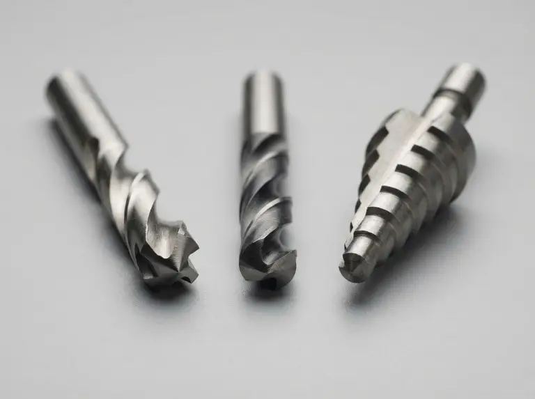
Spur-point bits — also called brad-point or dowel bits — are the best starting point for most thin-sheet work. The central point registers entry precisely. The outer spurs cut the perimeter before the flutes remove the core, which reduces lateral stress on the surrounding panel. For stock thinner than roughly 1.5 mm (a shop-floor starting point; verify against your material and bit), step drills are often more reliable. Their incremental cutting profile reduces the chance of the bit catching on first contact.
Standard wood bits should not be used on rigid thermoplastics. The self-feeding tip grabs aggressively and causes sudden pull-through on exit. Masonry bits are equally wrong: the percussion tip concentrates impact stress in a way that shatters brittle plastics.
When drilling acrylic, we confirm the bit is sharp before each run. A dull spur-point on acrylic generates more heat per unit depth than a fresh HSS bit on polycarbonate — which reverses the common assumption about which material is easier to work with.
Speed, Pressure, and Cooling — Setting Parameters for Thin Sheet
The right RPM for thin plastic depends on hole diameter and material type. No single speed works across all conditions. Treat the values below as shop-floor starting points and verify them against the bit manufacturer’s guidance for the specific polymer and diameter.
The relationship is inverse: larger holes need lower RPM. For holes under roughly 6 mm in acrylic, moderate-to-high RPM with light, steady feed pressure gives cleaner results than very slow speed with heavy force. For holes above roughly 10 mm, lower RPM prevents heat buildup at the wider cut perimeter. Sheets below roughly 3 mm should be drilled at the lower end of the range for a given bit size. The bit spends less time in contact with material, and through-vibration risk rises.
Feed pressure should be light and steady throughout the cut. Pulsing or increasing pressure to push the bit through creates the shear forces most likely to cause cracks. Let the drill advance under its own weight plus minimal applied load. Reduce feed rate in the final 1–2 mm before exit — this is when crack initiation and bit grab are most likely.
When teams assume higher speed shortens heat exposure, the result is often a melt zone at the hole perimeter followed by stress cracking as the material cools. We set speed parameters against material type and sheet thickness before any batch run begins, not after the first rejects appear.
Cooling matters most for acrylic and when drilling multiple holes in quick succession. Water applied at the entry point works in most cases. Cutting oil controls heat well but leaves residue that can affect bonding or surface treatment downstream — confirm the choice before use. For thin HDPE, active cooling is usually unnecessary and can cause surface whitening in some grades. For how heat affects acrylic, PVC, and polycarbonate more broadly, the rigid plastic machining heat response covers melt and stress behavior across the same material group.
Workpiece Setup, Backing Support, and Equipment Conditions
Good fixturing for thin plastic means both clamping the workpiece and placing a solid backing board directly beneath the hole — not just under the sheet edges. Skipping either step raises crack risk regardless of bit choice.
Thin plastic sheet flexes under drilling load even when the edges are clamped. For sheets below roughly 3 mm (the needed backing contact area depends on panel stiffness and feed force), a backing board directly below the drill point is essential. Close-grained timber or a scrap block of the same plastic both work. The board stops the sheet from deflecting as the bit loads it and gives the bit a controlled exit medium. Without it, the bit punches through unsupported material — one of the most common conditions linked to exit-face cracking.
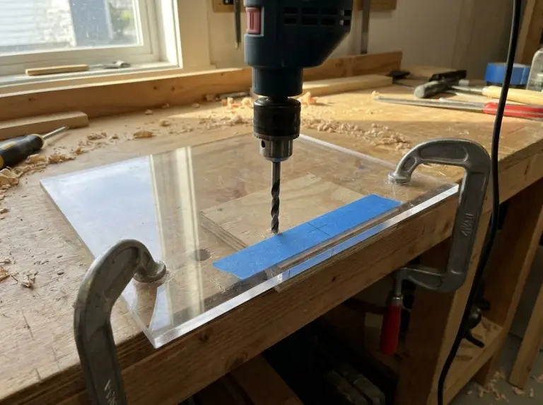
Masking tape over both the entry and exit faces helps the spur-point engage cleanly rather than skate across the surface at start-up. This is a low-cost, high-reliability step for thin acrylic and rigid PVC.
Equipment conditions change parameter requirements significantly. A handheld drill adds operator-variable feed pressure and lateral movement, raising exit-grab risk on thin sheet. Reduce speed deliberately in the final 3–5 mm rather than relying on consistent technique. A bench drill press allows depth-stop control — set the stop just above full exit to give the bit a controlled deceleration through the highest-risk moment. CNC-fixtured drilling gives the most repeatable feed control and exit-speed management, making it the best option for batch production of thin-panel components.
Holes closer than roughly twice the hole diameter from any sheet edge concentrate stress where material has less restraint. In these zones, reduce speed by roughly 30–40% from the normal starting point and confirm full backing coverage under the edge area. The minimum safe edge distance depends on the polymer’s notch sensitivity — verify against the material datasheet.
Pilot Holes, Sequencing, and Thermal Expansion Allowance
For holes above roughly 6 mm in thin plastic, a two-stage sequence — pilot hole then final-diameter pass — gives cleaner results than attempting full diameter in one step.
Size the pilot hole to clear the web diameter of the final bit. This removes material at the highest-stress center point before the full bit loads the sheet. It also gives the final bit a precise entry location and prevents skating. As a starting reference, a 2–3 mm pilot works for final holes up to roughly 12 mm in acrylic sheet below 3 mm thick. Verify this against the specific bit geometry and material grade.
Hole sizing for fasteners must account for thermal expansion. Thermoplastics expand and contract more than the metal hardware used with them. A hole drilled to the exact fastener nominal diameter will bind and stress the sheet during temperature cycling, leading to perimeter cracking over time. As a review starting point, an allowance of 0.2–0.5 mm over nominal diameter is common in light-duty room-temperature assemblies. Larger allowances apply as the polymer’s thermal expansion coefficient and service temperature range increase. Confirm the required clearance against the material specification and assembly conditions.
We confirm hole sizing during drawing review — especially for assemblies where plastic panels are fastened with metal hardware in environments with significant temperature variation.
Mistakes That Produce Cracking After the Bit Exits
Some error patterns cause fractures that appear only after drilling is done. They are easy to misread as material defects.
Not reducing speed at exit is one of the most consistent causes of delayed cracking. When the bit clears the exit face, resistance drops suddenly. The bit can torque the surrounding panel before the operator can respond. On a drill press, a depth stop set just above full exit gives the bit a controlled slowdown. On a handheld drill, deliberate speed reduction in the final approach requires awareness — not feel.
Removing the backing board before the workpiece cools adds stress to heat-sensitive materials like acrylic. Letting the drilled part cool in place before handling costs little time and removes a common source of deferred cracking in production runs.
Leaving swarf in the hole without clearing it causes the flutes to pack. This raises both heat and cutting pressure at the drill face. Retract the bit every few millimeters to clear chips — especially when drilling at an angle, through stacked thin sheets, or without a water-based coolant.
Conclusion
Drilling thin plastic without cracking requires three setup conditions to be in place before the first cut: bit geometry matched to the polymer, speed and pressure set for the sheet thickness and hole diameter, and fixturing that removes flex and controls the exit moment. When any one of these is missing, cracking follows — immediately or after a delay that makes the source hard to trace during production review.
At IPG, our core work is plastic size reduction — including the design and manufacture of plastic crusher equipment for thermoplastic processing lines. This direct experience with how polymers respond to mechanical stress informs how we approach downstream fabrication steps, including precision drilling in thin-wall plastic housings and equipment assemblies. In production contexts involving drilled fastener points or vent features, we find that exit-speed control and consistent backing support are the two process variables most often left undefined in initial setup documentation — and the two most directly linked to first-run part rejection. We confirm both against the specific polymer, sheet thickness, and hole pattern before volume runs begin.
If your operation involves drilling thin plastic panels as part of an equipment assembly or fabrication process, sharing the material type, sheet thickness, hole diameter, and fastener or clearance requirements lets us help align the process variables before your production run starts. Reach out to our team with your specifications.
FAQ
Can I use a step drill on thin acrylic?
A step drill can work on acrylic, but it is not the first choice for sheets below roughly 3 mm. Pair it with a pre-drilled pilot hole and reduce speed as each step engages.
Is there an alternative to drilling for thin plastic film below 0.5 mm?
A heated punch or hollow die punch gives cleaner results at this thickness. Rotary drilling is hard to control on sub-0.5 mm film — the panel deflects before the bit can cut. This content does not cover film applications in that range.
Does plastic temperature at the time of drilling affect crack risk?
Yes. Cold acrylic stored in an unheated space is more brittle and more prone to fracture under sudden bit engagement. Allow sheet material to reach room temperature before drilling, especially where stock is stored in cold warehouses.
Can a rotary tool be used on thin plastic?
Rotary tools at high RPM commonly cause melt and crack damage on thin thermoplastic sheet. For small-diameter holes in thin sheet, a variable-speed drill with a spur-point bit and a backing board gives more control.
How do I stop the protective film on acrylic from wrapping the bit?
Leave the protective film on during drilling. Score around the entry point with a sharp blade first. Retract the bit often to stop the film from peeling back and wrapping the flutes. Remove the film only after drilling and edge finishing are done.